
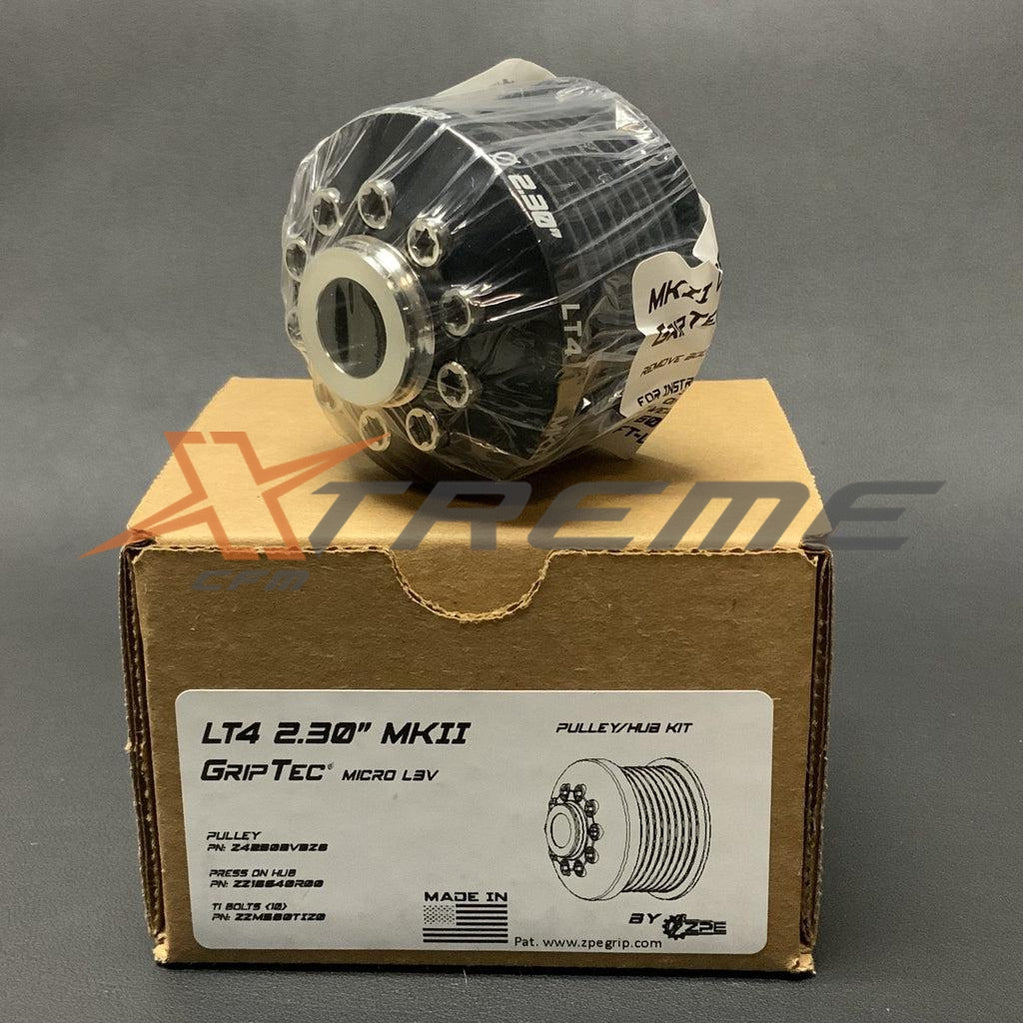
Manual - CTS-V (V3) Fender Expansion Tank Kit - XCFM-10119
Below are the installation instructions to our Cadillac CTS-V (V3) fender wanter tank kit.
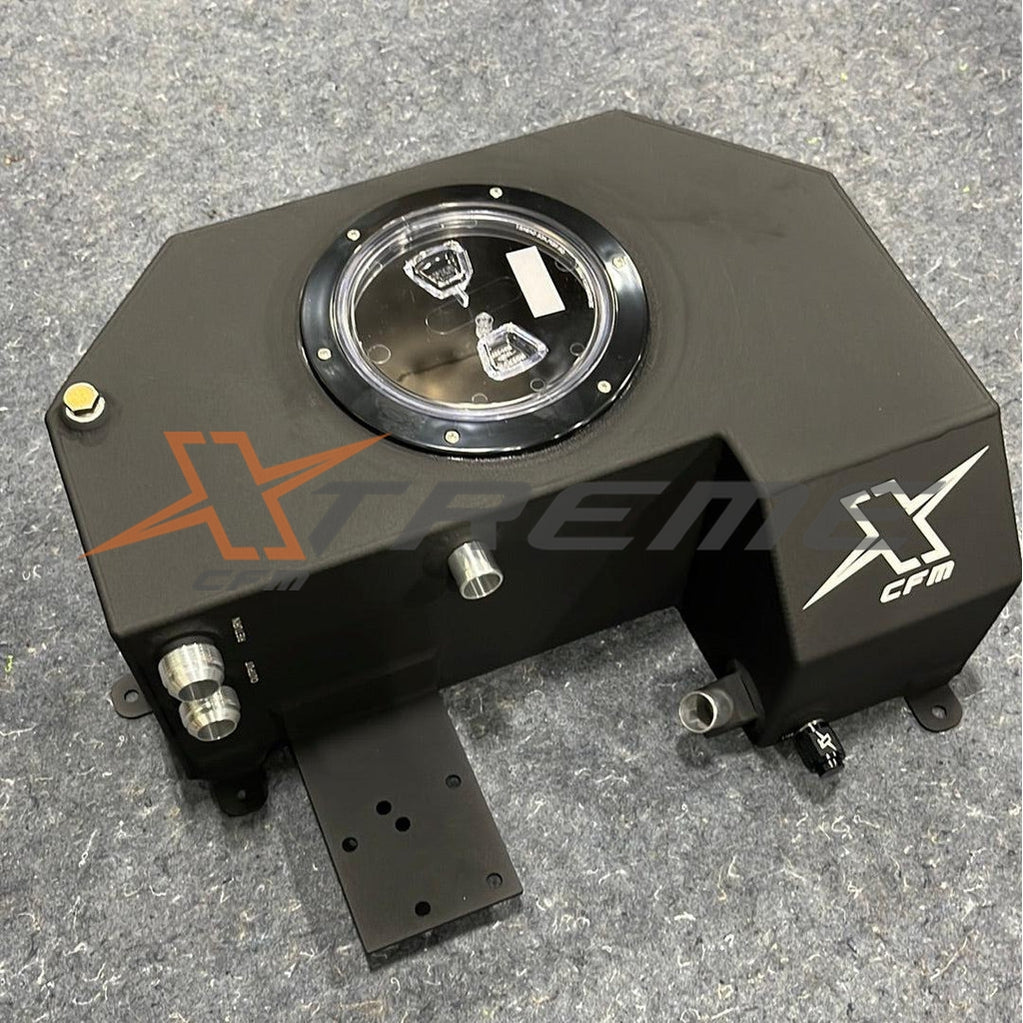
- The purpose of an expansion tank is to boost the fluid volume in the intercooler cooling system. It's not meant for filling, but rather to increase capacity. The tank adds 1.5 gallons to the entire system and is located far from the engine bay heat to regulate intake air temps in the blower.
- To begin, jack up the front left of the car so that the tire is off the ground. Remove the tire, and then proceed to remove the wheel well liner. The liner extends from front to back and covers the wheel area.


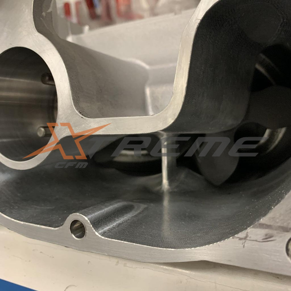
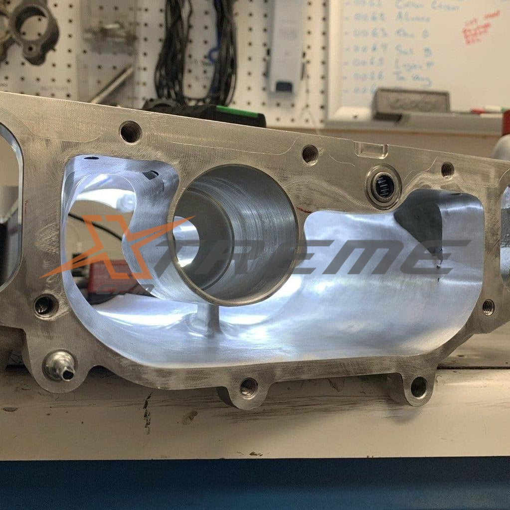
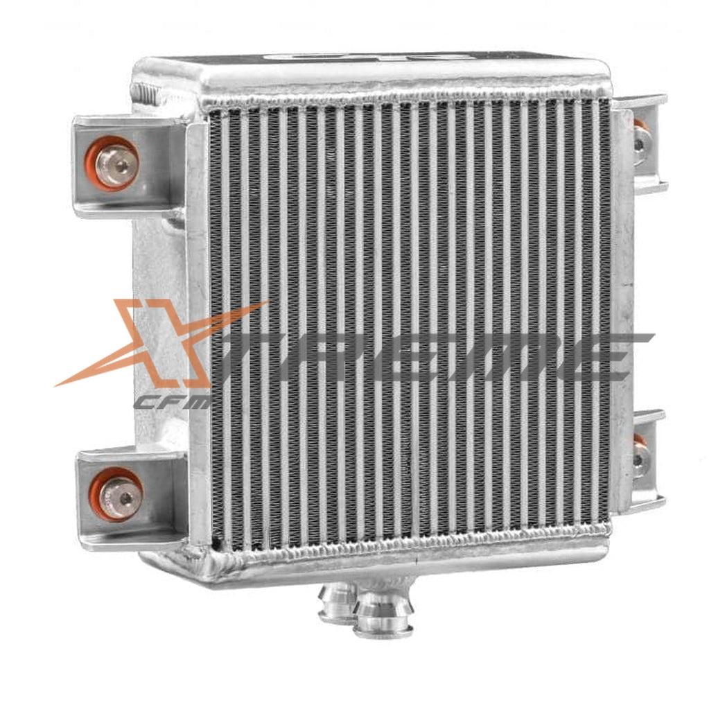
- You should now be able to see everything, including the open space in the fender behind the tire and the front left intercooler heat exchanger.


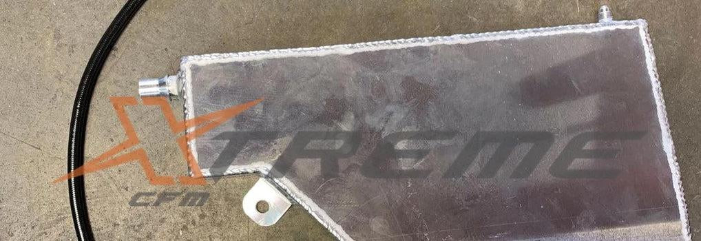
- At this point, we will begin by installing the tank first. There is a factory hole at the top where you will install the M8 Nutsert. If you have access to a 90-degree nutsert tool, that would be best. If not, use the one supplied with the kit. The tool works by pulling and compressing the nutsert to grab around the hole, providing you with a thread point for a bolt. Once installed, remove the giant foam bar at the top by pulling it out; it is only laying in there. Now we are ready to fit the tank. Slide the tank in, and with the supplied longer M8 bolt and machined spacer, thread the upper bolt into the nutsert. You can drive the bolt in almost all the way, but do not tighten it yet. Note that if the tank is a little too tight to slip in on its own, you can try one of two things. First, grab some channel locks and bend the middle frame tab forward to allow more room for the middle of the body to slip past, as shown in the picture. Second, loosen the fender and allow the tank to slip in that way.


- Next, let's move on to the lower mount and bracket. The bracket supplied with the kit can only be installed in one direction. The single hole on the bracket should be on the frame side and should be secured with the self-tap bolt provided. The side of the bracket that is slotted with a small hole on the very end should be on the tank side and should use the Long M8 bolt and half-inch spacer.
Start by threading the M8 bolt through the slotted section of the bracket and spacer and into the standoff on the tank. Do not tighten it yet. On the frame side, position the self-tap bolt somewhere in the middle of the two spot welds, ensuring that you have a good range of motion on the bottom of the tank. The goal is to be able to slide the tank back and forth to pivot and allow the top right of the tank to move away from the inner top fender. You'll see how to do this when you slide the bottom of the tank back and forth.


- Now that you have located the tank in a position you like, you may remove the tank and install the top bleeder line and foam backing strips. Make sure the bleeder line is pointing toward the front of the car. Go ahead and snug the -4AN on the top of the tank. With the foam strips, you will want to lay out two strips like in the picture. Remove the backing and stick the strips to the tank. This is to aid in any tank vibration or noise. You can reinstall the tank. Tighten the top mounting bolt first, then position the bottom where you feel it’s not hitting the fender and tighten that bolt as well. The tank should be solid and not moving.


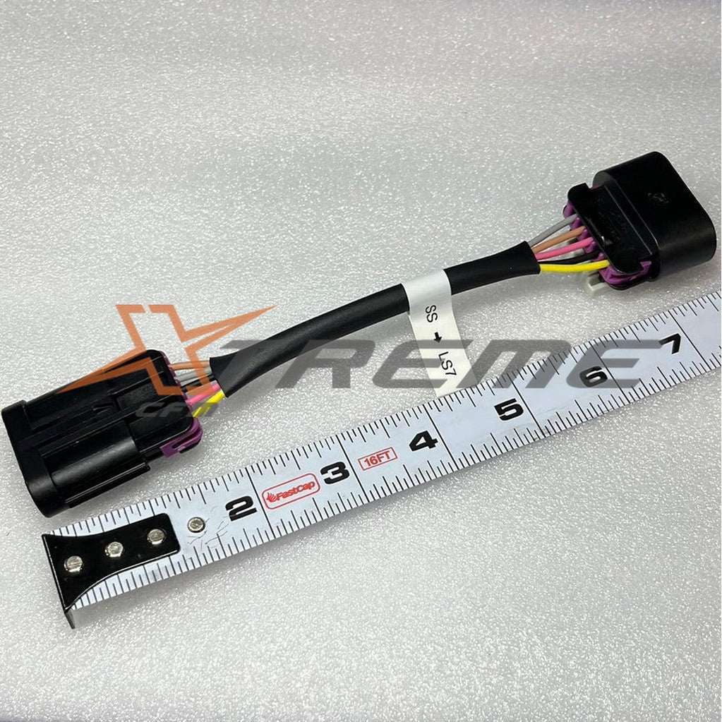
- Now, let's move on to running the water lines. Above the factory HX, there is a piece of foam that you will need to cut out a portion of in order to run the lines. The picture gives you an idea of where to cut. In the box, you will find two lines. One line has a 90-degree quick connect fitting, which goes to the bottom of the tank. The other line has a straight connector and goes to the top of the tank. Apply the supplied lube to the upper and lower fitting on the tank, and then slide each connector onto its fitting until you hear it click.


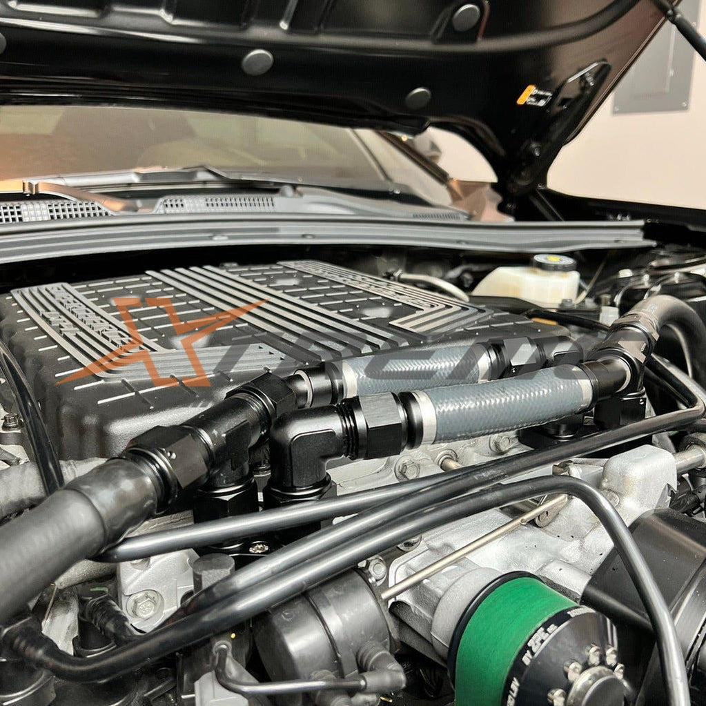
- Both lines will run up and over the wheel area frame and towards the front of the car. There will be a channel where you can run both lines side by side. As the lines continue forward to the front of the car, you will see a channel that comes down in the middle of the headlight and other areas. Both lines will come from the upper area and plug into the required lines as they come down.


- This is where you will tie into the factory lines and fittings. The line going into the heat exchanger is the direct line from the intercooler pump on the car and will have a silver factory clamp on it. Pinch the clamp and slide it back since we will be reusing it. To break the rubber hose free from the 90-degree factory fitting, twist the hose or pull it gently until it comes free. Only a small amount of fluid will come out, but it helps to have a pan ready under the car just in case a lot comes out.
Both lines are marked where they go, so the pump line runs to the open rubber line you took off the heat HX fitting. First, run the line to the HX with the supplied clamp, then connect the 5/8ths barb to the pump line with the factory silver pinch clamp. Once done, use zip ties to tie the lines together at certain points to keep them together. The mounting bracket on the bottom of the tank has a small open hole. Take the special push-pin-style zip tie, wrap it around the hose first to get it started, then push it into the bracket. Tighten the zip tie once you are happy with its position.


-
You are now done with the tank and line installation. Move up to the engine bay area, and you will see the bleeder line you ran forward alongside the frame area. You will use this bleed line to fill and bleed the system. Filling the LT4 system can be a little tricky, so be patient with it.
There are many ways to fill the system, including using a large funnel and a rubber hose to mount to the bleed port next to the blower. You can then use a long straw or stick to press down on the check valve to open it. If you have a scanner or a way to activate the pump, this is the easiest method to run it. However, if you do not, here is a way to jumper the relay for those who do not have access to a scanner or software to run the pump. Remove the pump relay in the engine fuse box, and with a wire or a jumper device, jump pins 30 and 87 to trigger the pump. This is a quick and easy way to operate the pump.


-
Bleeding the system will take some time, so go slow and find a method that works best for you. As the pump activates, it will draw in coolant and start to fill the tank. Make sure you are opening the check valve by pressing down on it, or it will remain shut. Once you see the fluid slow down or no longer filling the system, stop the pump and release the tank pressure by opening the bleeder line. You should hear pressure releasing, which will help remove all the air as you keep adding in coolant. Repeat this process until you are confident that you have a full system.
Again, it's all about finding the method that works best for you. Once you have finished bleeding the system, check for leaks everywhere. If no leaks are found, go ahead and reinstall the liner and the tire. You have now added 1.5 more gallons to the system and will have much better temperature control on the blower. Happy racing!
NOTE: It is important that once the pump is off that you do a final burp to the system by pushing the check valve on the fill.
If you have any questions please contact us!
- Choosing a selection results in a full page refresh.